
Published September 16, 2026 · Updated September 17, 2026
In short: A twist-pin platform can take a C-type or pi-type filter network, mixed coaxial contacts for signals up to about 1 GHz, or a 300 bar air channel routed down one side of the insert, none of which require a new shell or mounting dimensions. Extending an existing, qualified family is usually faster than qualifying a new one. The result only performs as well as the contact-to-wire joint, so lock down the termination method before releasing the drawing.
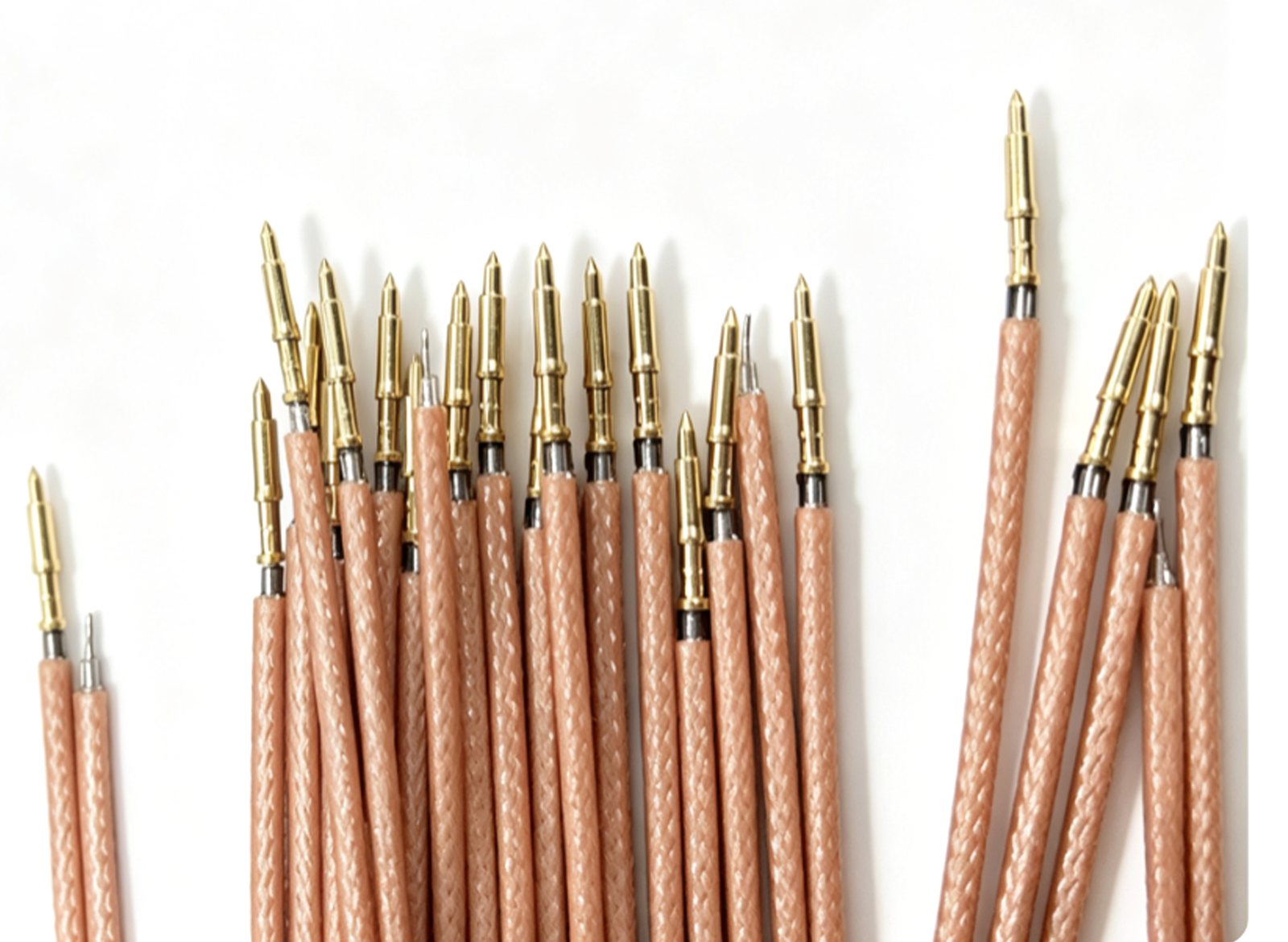
A twist-pin contact is a bundle of twisted wires held in a sleeve, so the mating pin touches it along several lines instead of at one point. That construction is why twist-pin connectors, also written twisted-pin, hold contact resistance steady under vibration, and why they became the default micro-connector in airborne, missile and space equipment.
Almost every requirement that has landed on our desks in the past two years sits around the contact system rather than inside it. Systems need conducted interference suppressed, video and bus signals carried, and a gas supply routed through the same bulkhead as the signals. None of those needs is new. What changed is that program schedules no longer allow a new connector family.
One note on perspective. Lanneas builds crimping, welding and inspection equipment for connector assembly. We do not sell connectors. So the view below comes from the production floor, from sample boxes customers send us and the joints we measure on them, rather than from a product datasheet.
In short: a twist-pin connector platform can take a filter network (C-type or pi-type), mixed coaxial contacts for signals up to about 1 GHz, or a 300 bar air channel on one side of the insert, all without changing the shell or mounting dimensions. The extension only performs as well as the contact-to-wire joint allows.
Why extending an existing platform usually wins
Replacing a micro-connector with a different family is a systems decision, not a component swap. The shell interface changes, so mounting holes, harness routing and the assembly sequence change with it. Then qualification starts over: vibration, thermal cycling, mating durability, plus whatever program-specific testing applies. That is usually several quarters of work spent solving a problem that was never about the connector.
An extension keeps the shell and the mounting dimensions. The insert changes, contacts are replaced or mixed, and the harness shop keeps working to the same interface definition. In most cases a filtered or mixed-insert part drops into a socket that was designed for the standard part.
There is a limit to this, and it is worth stating plainly. An extension can only use volume that already exists inside the shell. When a filter's dielectric stack, a coaxial cavity and a gas channel all compete for the same space, something has to give. That is the point where a new shell design is the honest answer rather than a longer proposal.
Filtering: C-type and pi-type networks built into the contact
Both networks put capacitance between the contact and the shell, so conducted interference is shunted to ground at the connector instead of traveling down the harness and radiating from it. Fixing EMC at the connector is usually cheaper than chasing it on the board.
A C-type network uses a single feed-through capacitor from contact to ground. It is small and simple, and it is the usual choice for cost-sensitive programs working in the lower bands.
A pi-type network is capacitor, inductor, capacitor. It gives a wider stop band and more insertion loss, and it pays for that with more dielectric volume inside the insert.
The practical rule is to match the network to the band you have to suppress, not to the largest attenuation figure on a catalog page. A number quoted at one nominal frequency says very little about a band that spans a decade.
Interchangeability is the part of filtering that gets underestimated. A filtered contact has to mate at the same interface as the standard twist-pin contact, and the shell dimensions cannot move. Lose that and the reason for doing the extension disappears, because the system-level interchangeability test will not pass and the whole connector goes back into the harness redesign you were trying to avoid.
Two parameters to lock before the drawing is released
Rated and withstanding voltage. A filter network consumes insulation margin that the unfiltered contact had spare. A contact that passed dielectric withstanding at the standard rating may not pass it with the network installed, especially at altitude where the margin is already thin.
Insertion loss against the working band. Ask for the curve, then compare it with the frequencies your noise source actually produces. If a supplier only offers one attenuation figure, treat it as marketing until the curve arrives.
Coaxial contacts for signals below 1 GHz
A single contact sitting in dielectric has no defined impedance. Feed it a video signal or a fast bus and the impedance discontinuities along the path appear as reflections and crosstalk, and the longer the run, the more obvious it becomes.
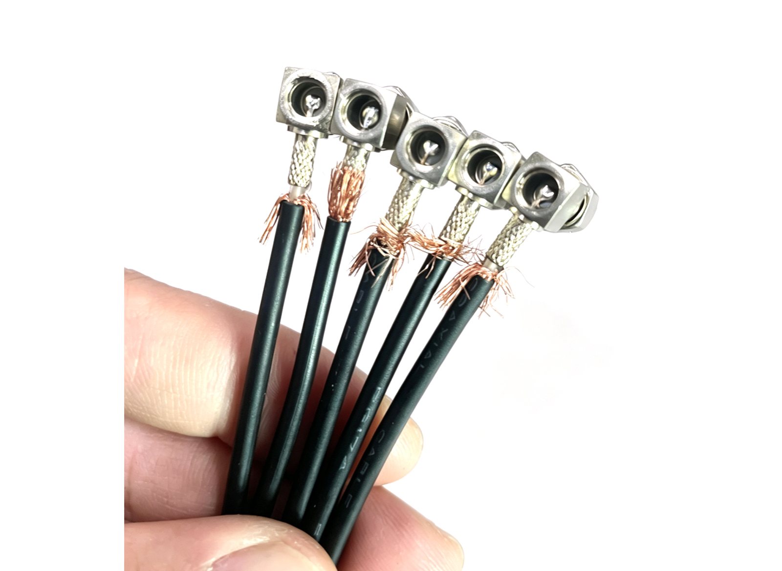
The standard answer is to mix coaxial contacts into the same insert. J599 series 12 and 16 size coaxial contacts are the usual building blocks. J599 is the Chinese series corresponding to MIL-DTL-38999, and its coax contacts already carry published characteristic impedance and VSWR data.
Working with a standardized coax contact buys three things. You inherit the electrical characterization instead of generating it. Signal performance below 1 GHz is stable enough for video and the usual avionics buses. And one connector carries both power contacts and RF, which removes a separate high-frequency port and the mounting space it would have taken.
Two details give projects trouble. Coax contacts need dedicated termination tooling and access from the rear of the shell, so wire exit direction has to be agreed with the harness shop before the cavity layout is frozen, not after the first samples are built. The positions of the coax cavities relative to the signal cavities also decide how easily a contact can be replaced later. If the unit has to be repairable in the field, that belongs in the layout brief at the start.
Where this approach stops is around 1 GHz. Above that, contact geometry and insert design turn into a different engineering problem, and it is better to hear that at the proposal stage than at the qualification stage.
Air paths at 300 bar, routed down one side of the insert
The third recurring requirement is pneumatic. A control-surface actuator needs a gas supply crossing the same bulkhead as the signal harness, and the space inside an airframe for a separate hose run usually does not exist.
The design we build tooling for puts the high-pressure channel on one side of the insert rather than through the middle. Contact density is highest at the center, so a channel through the middle would cost signal cavities on both sides of it. Moving the channel to one side leaves the opposite side of the insert fully usable and keeps the connector envelope small.
300 bar, about 30 MPa or 4,350 psi, is the pressure most programs specify today. At that level the sealing face geometry, the tube pressure rating and gas-path cleanliness need to be designed and verified together rather than negotiated as separate line items.
Two effects that are easy to miss
Deformation under pressure cycling. The shell and insert deflect slightly as pressure rises and falls. The deflection has to stay small enough that contact normal force does not drift out of its window. That is a mechanical analysis on paper, but it is confirmed on the bench with resistance monitored during cycling, because the analysis assumes a seal that behaves as modeled.
Seal compatibility with the real medium. A factory leak test at rated pressure proves the joint was gas tight on the day it was made. It says nothing about a seal that has sat in the working gas for a year. Aging tests should use the actual medium, and for some programs they should also use the actual temperature profile.
Comparing the three extension routes
| Extension | How it is implemented | Parameters that decide acceptance | Effect on the shell |
|---|---|---|---|
| Filtering | C-type or pi-type network integrated on the contact | Insertion loss over the working band, rated and withstanding voltage | None. The filtered part keeps the same mounting and mating interface as the standard part. |
| Coaxial | J599 series 12 or 16 size coax contacts mixed into the insert | Characteristic impedance, VSWR, signal band below about 1 GHz | Same shell and mounting. Insert cavity layout changes, and the rear termination needs tooling access. |
| Air path | High-pressure channel on one side of the insert | Working pressure (300 bar typical), leak rate, seal compatibility with the medium | Channel occupies one side of the insert. Mounting dimensions unchanged. |
The routes combine. A filtered insert with an air channel on one side is a routine request at the proposal stage. The constraint is the volume inside the shell, not the combination itself.
The step most extension projects underestimate: the contact-to-wire joint
Everything above describes what happens inside the connector. The signal or the gas still has to leave the contact and travel down a wire, and that joint is where we spend most of our time with customers.
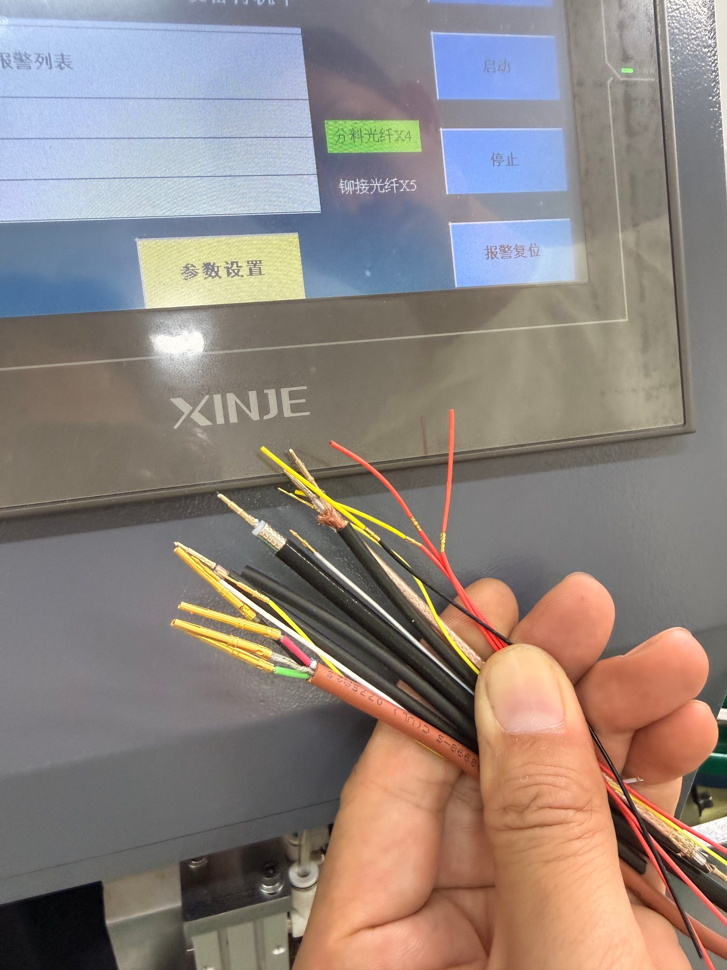
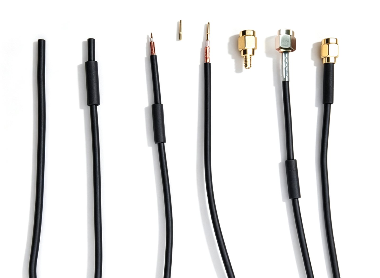
A typical sample box contains the same connector built two ways. One set has center pins joined by soldering. The other has pins joined by riveting or crimping. Side by side they look like a process comparison, and that is exactly what they are.
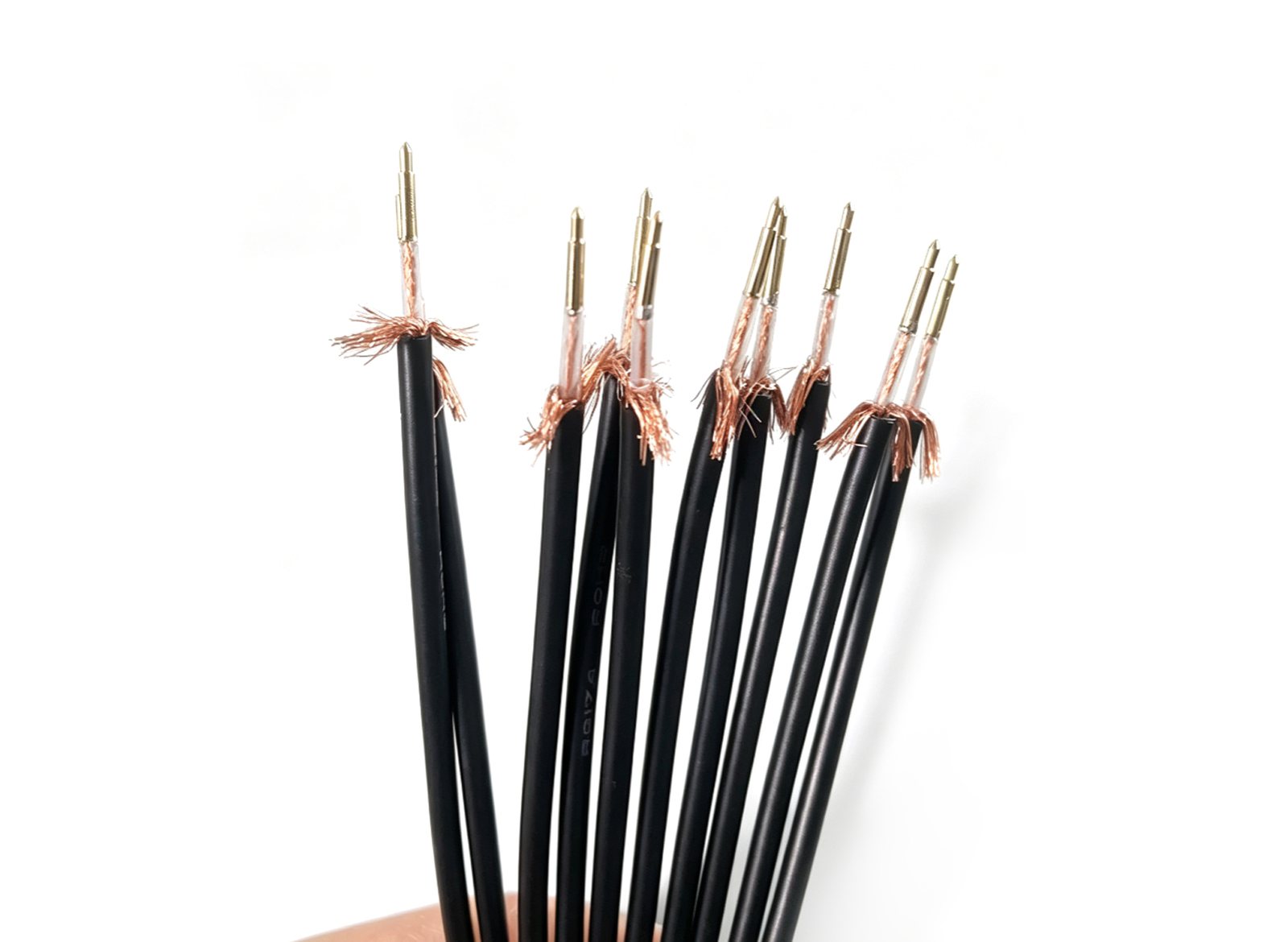
Soldered joints. Solder is the right answer for very fine stranded conductors, for pin and wire combinations that cannot be crimped, and for small lots where a die set is not worth building. Its problems are process problems. A cold joint can pass a pull test and still fail in thermal cycling. Wicking stiffens a flexible section that was the reason for choosing that wire in the first place. Flux residue ends up where it cannot be cleaned. And the joint quality varies with the operator in ways no drawing captures.
Riveted and crimped joints. A servo press with force monitoring deforms the pin or contact onto the conductor inside a stored force window. The joint is made cold, so there is no flux and no heat-affected zone, and the force curve is recorded per part, which is what makes the process auditable a year later. The trade-off is tooling. Die geometry has to match both the conductor and the pin, and the force window has to be established on real samples before it goes into a recipe.
What we measure on a sample set before quoting a process
- Strand condition after stripping. Cut strands are a defect that crimping cannot repair.
- Force curve against the stored window, part by part, not averaged over a batch.
- Pull-off retention, to the value in the customer's own acceptance document.
- Center-pin concentricity, for coaxial parts.
- Braid fold-back and dielectric condition, since damage there surfaces as return loss and never as a failed pull test.
- For RF assemblies, VSWR or return loss measured after joining, not on the incoming cable.
If you want to compare process capability on paper first, the machines that do this work are the LP-CR174 center-pin riveter for 174 and RG58 coax lines, the LP-MC2024 twist-pin crimper for 0.3 to 1.5 mm contacts at up to 1,200 pieces per hour, and the ANT-15 cell for SMA, SMB and GPS antenna assembly across 15 stations.
What to freeze before the drawing is released
- The frequency band or the noise source for any filter network, not just a target attenuation figure.
- Rated and withstanding voltage for the filtered contact, re-verified with the network installed.
- Coax contact type, cavity count and wire exit direction, agreed with the harness shop.
- Working pressure, gas medium and a cleanliness class for the air path, plus an aging test with the real medium.
- Contact normal force measured during pressure cycling for any part with an air channel.
- The joining process for each contact type, soldered or riveted, with the force window or solder profile recorded and stored.
- Interchangeability evidence: the extension part and the standard part tested in the same socket.
- The retention and pull-off values the acceptance document actually states, which is not always the same as the note on the drawing.
Send an interface definition and the extension parameters, and we will come back with the route that fits, plus the sample checks it needs before anyone commits to tooling.
Related equipment and guides
Extending a Twist-Pin Connector: Filtering, Coaxial and Air-Path Options — FAQ
Can a twist-pin connector carry a filter without changing the shell?+
What signal frequency suits coaxial contacts in a twist-pin insert?+
How much pressure can an air path through the insert carry?+
Why does the contact-to-wire joint decide the result?+
What should be frozen before releasing the drawing?+
Related reading
Twist Pin vs Standard Terminal Crimping: What Buyers Should Know Resources
Differences between twist pin and standard terminal crimping, and why CCD inspection matters.
RF Connector Automation: How to Choose the Right Equipment (2026 Guide)
A practical, no-fluff guide to automating SMA/SMB, 174/RG58 and coaxial connector assembly — when it pays off, the specs
Wire Sequence Detection & Laser Marking for Military Connectors Resources
How vision detection and laser marking prevent wire sequence errors in high-reliability harnesses.
Twist-Pin Wire Crimping Equipment
A twist-pin crimping machine for 0.12–0.2 mm² wire, built for micro-rectangular connector makers. It solves the producti